Programming my Hello Board
I use the Arduino IDE to program my helloboard, the interface of this IDE is really "noob" friendly and the community behind it is juste immense. So for me, a beginner who is on a deadline, it was a no-brainer to go with this IDE. ("The arduino IDE is a code editor with features such as text cutting and pasting, searching and replacing text, automatic indenting, brace matching, and syntax highlighting, and provides simple one-click mechanisms to compile and upload programs to an Arduino board.") As explained on the "
wiki".
It support C and C++ language and using special rules of code structuring. It also provide a software library coming from the
Wiring project. It is very similar from the software
processing but is made for programming hardware such as sensor, microcontroller ans else while processing is made to create interactive interface and GUI.
All I wanted to do with my helloboard is a simple program that blink my led when I press the pushbutton. So looking at my board design I already know wich pin will be used in my code.
![]()
We know that I will use my physical pin 5 (pin 8 on the arduino IDE) for my LED, and the physical pin 10 (pin 3 on the arduino IDE) for my Button.
Knowing that we can start our code by defining our pin using this line of code.
const int ledPin = 8 ;
const int buttonPin = 3 ;
The const prefix mean that the variable won't change during the time of the code running, the variables are "constant"
The "int" prefix mean that the variable is an integer, which is a full number 0,1,2,3 are all integer, while 2.1 would be a float number.
Next we will prepare the variable to read and check the button and led status.
int buttonState = 0 ;
bool led_on;
buttonState = 0 just set the fact that we will later use a variable called button state, as you can see this variable ain't constant, because the state of the button will change eache time we will press it.
A boolean is a way to check if a fact is true or false at any time in our code. In our case, the led is ON : true or false?
Now that our variable are set, we can start writing our actual code, we first need to setup the code that run only once at the begining of the reading of our code, we called that part the setup and once it run, it won't be read again until we reset our code.
pinMode(ledPin, OUTPUT);
pinMode(buttonPin, INPUT);
This is pretty straightforward, we set the ledpin as an Output pin and the buttonpin as an Input.
Now we have to create a Loop, a loop is the part of the code that will be read over and over again, it is the actual "action" that the code will do.
if (buttonState == LOW) {
digitalWrite(ledPin, HIGH);
}
else {
digitalWrite(ledPin, LOW);
}
}
Here we are, now we have to test the code, normally everything should work.
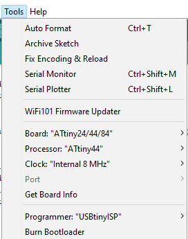
To insert the code we first need to set up our Arduino IDE to program our attiny44. So we will do just like we did with our ISP.
Into the board tab we will go and select our Attiny44, make sure we use our internal 8mhZ oscillator and set the programmer as a tinyusb since we will be using our FabISP to program the board.
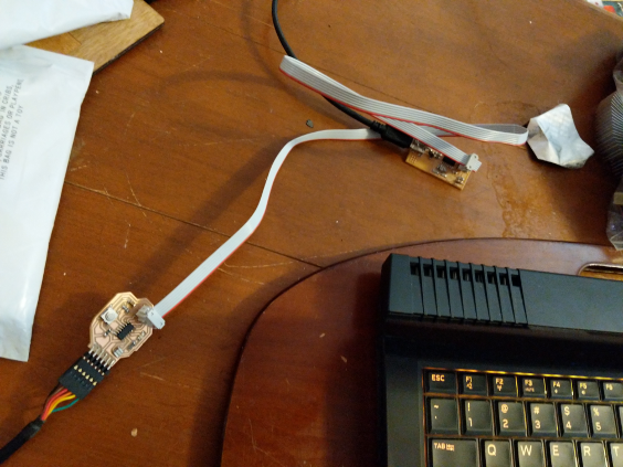
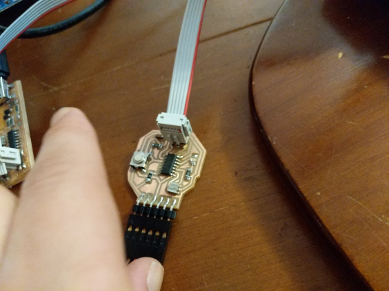
Next we will plug in our FabISP to our HelloBoard :
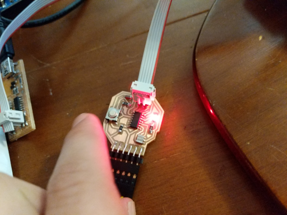
I upload the code and guess what?
It worked!!
Here is the final code:
  // Set Pins
const int ledPin =  8 ;
const int buttonPin = 3 ;


int buttonState = 0;         // variable for reading the pushbutton status

void setup() {
  // initialize the LED pin as an output:
  pinMode(ledPin, OUTPUT);
  // initialize the pushbutton pin as an input:
  pinMode(buttonPin, INPUT);
}

void loop() {
  // read the state of the pushbutton value:
  buttonState = digitalRead(buttonPin);

  // check if the pushbutton is pressed. If it is, the buttonState is HIGH:
  if (buttonState == LOW) {
    // turn LED on:
    digitalWrite(ledPin, HIGH);
  }

  else {
    // turn LED off:
    digitalWrite(ledPin, LOW);
  }
}